Top Trusted Rotor Manufacturing Equipment Factories & Factory
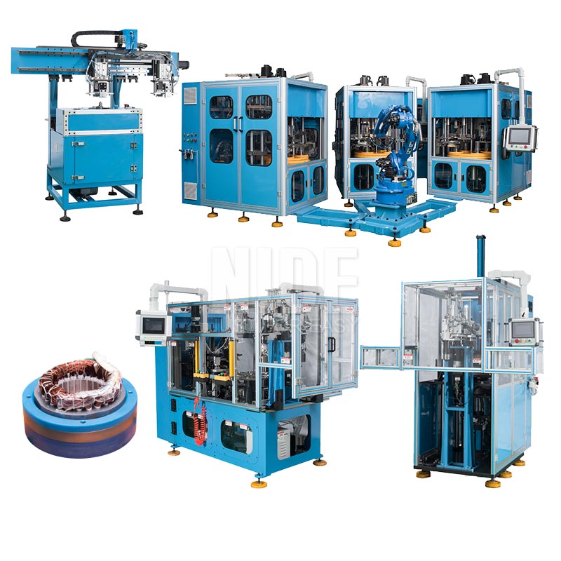
Precision dynamic balancing, automated flyer & hairpin winding, automated magnet inserting, and zero-defect commutator finishing engineered for global Tier-1 electric motor production lines.
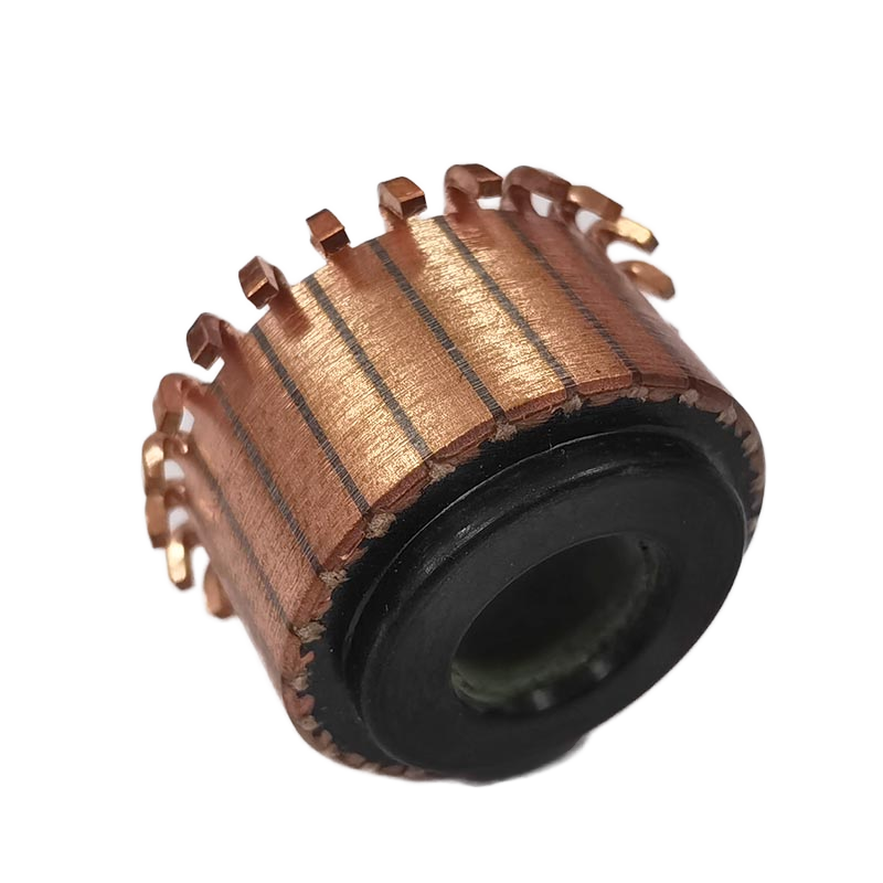
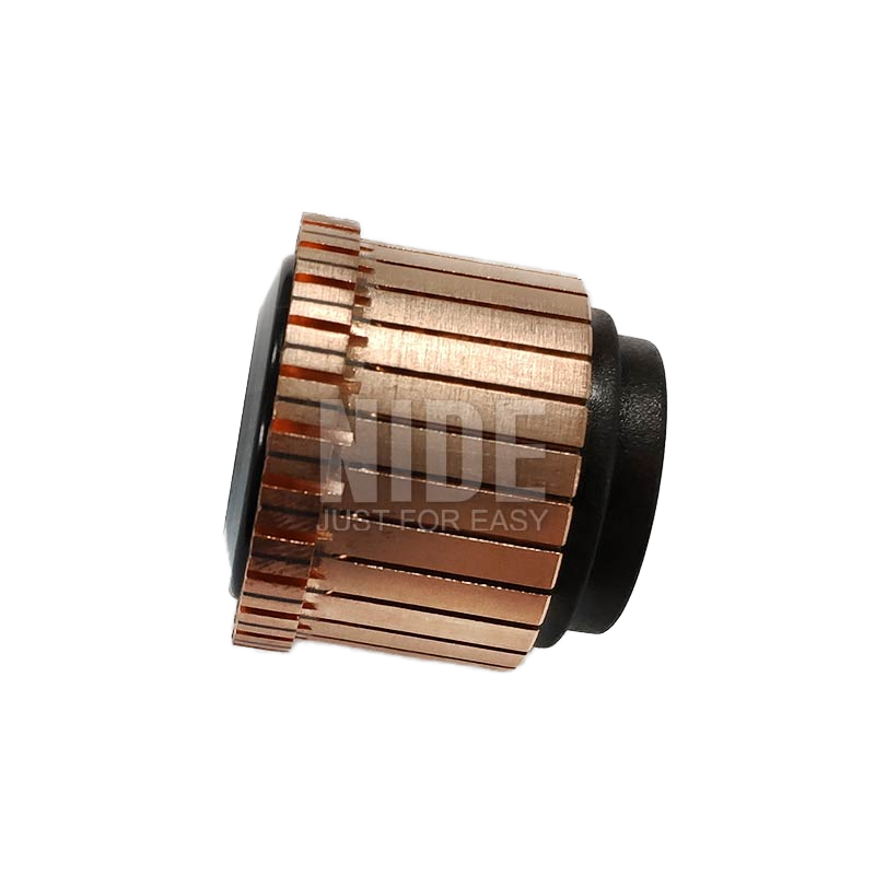
Precision-molded mica-insulated commutator designed for high-RPM universal armatures, offering superior thermal stability, low spark erosivity, and dynamic balance integrity.
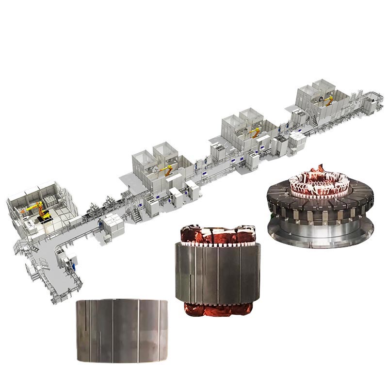
Flexible semi-automated to fully automated assembly cell for three-phase induction stators and squirrel-cage rotor shafts, optimized for rapid frame-size turnover.
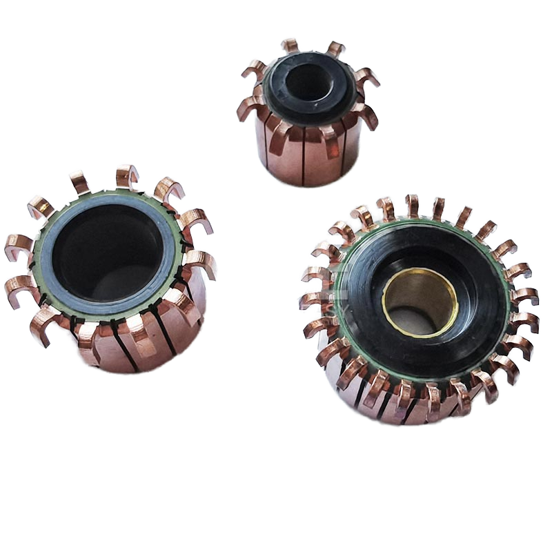
High-voltage rated collector ring segment assembly with reinforced steel locking rings, offering superior peripheral speed durability up to 45 m/s without segment lifting.
Engineering the Modern Rotor: Manufacturing Tolerances & Assembly Systems
The manufacturing architecture of electric motor rotors is undergoing rapid transformation, propelled by the strict power density requirements of automotive electrification, industrial variable-frequency drives, and cordless power platforms. Achieving rotational velocities exceeding 20,000 RPM in interior permanent magnet synchronous motors (IPMSM) and high-power universal motors requires machinery capable of maintaining micron-level dynamic eccentricity tolerances while preserving magnetic and electrical boundary layer insulation.
1. Shaft Press-Fitting and Laminations Stacking Dynamics
The mechanical structural loop starts at the rotor shaft and lamination stacking station. Rotor laminations stamped from high-permeability, non-grain-oriented silicon steel (typically 0.20 mm to 0.35 mm in thickness) require precise skewing angles during core building to mitigate cogging torque. Advanced rotor production machinery integrates servo-controlled hydraulic or pneumatic-hydraulic press-fitting systems with closed-loop force-displacement monitoring. Real-time load-cell tracking detects any galling, lamination burr deformation, or run-out exceeding 0.008 mm TIR (Total Indicator Reading) before downstream winding or magnet insertion occurs.
2. High-Speed Flyer Armature Winding vs. Needle Automation
In wound-rotor topologies and universal DC motors, dynamic coil insertion requires servo-synchronized dual-flyer winding heads operating at speeds up to 3,500 RPM. Tension control is paramount: excessive tension induces wire stretching, reducing the cross-sectional conductive area and creating hot spots, whereas inadequate tension leads to coil displacement under centrifugal acceleration. The modern equipment benchmark employs magnetic hysteresis or closed-loop digital servo tensioning to ensure consistent slot-packing factors (>75%). For brushless PM rotors and outer-rotor hub motors, robotic multi-axis needle winders navigate confined internal slots with direct wire laying, eliminating end-turn crossovers and achieving compact envelope dimensions.
3. Fusing, Commutator Diamond Turning, and Undercutting
For commutated assemblies, the electrical junction between the magnet wire and copper hook segment must be formed via high-precision resistance fusing or micro-TIG welding. Thermal profiles must prevent softening of adjoining mica insulation layers. Downstream diamond turning utilizing polycrystalline diamond (PCD) inserts cuts the commutator runout to under 0.003 mm, with a surface finish Ra < 0.4 μm. Automated high-speed optical undercutting units subsequently profile the insulating mica slots, clearing copper flash and burrs with laser or high-speed rotary saws, thereby preventing commutator short circuits during brush break-in.
4. Permanent Magnet Assembly, Retention Sleeving, and Dynamic Balancing
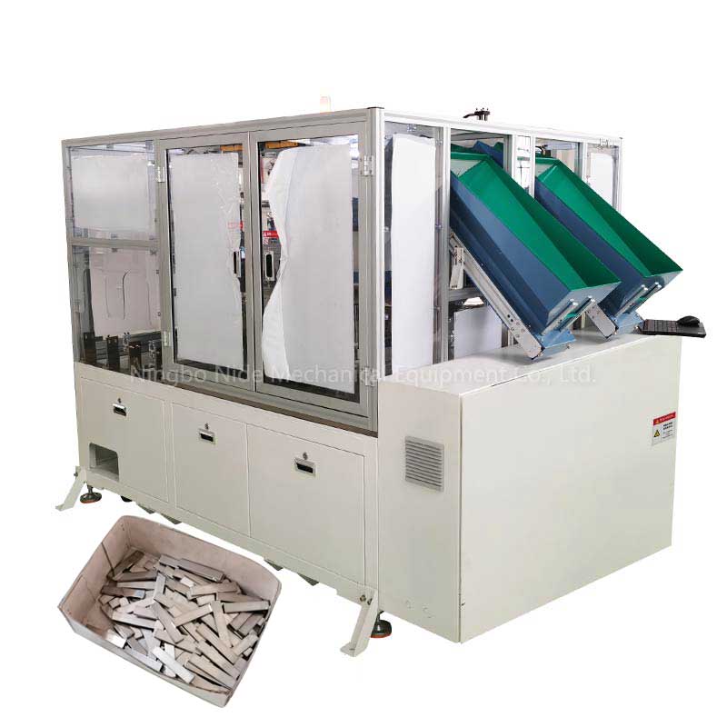
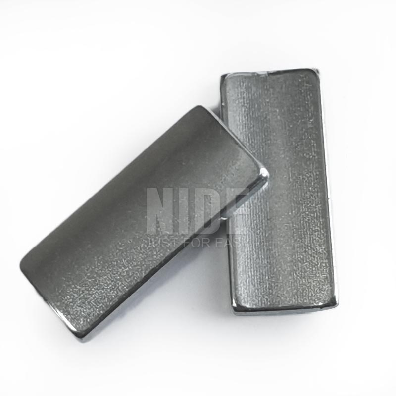
Surface-mounted PM (SPM) and internal PM (IPM) rotors require specialized automated handling to manage high-remanence NdFeB blocks. Dedicated magnet inserting stations apply automated two-part epoxy or structural anaerobic adhesive via positive displacement valves, index the core, and press magnets into laminated cavities with optical confirmation of magnetic orientation. For ultra-high-speed designs, automated carbon-fiber tension winding or stainless-steel sleeve thermal shrink-fitting guarantees mechanical integrity against centrifugal rupture. The sequence concludes at an automated multi-plane dynamic balancing station where material is removed via CNC milling/drilling or added via UV-curable balancing putty, achieving ISO 1940 Grade G1.0 balance specs.
Strategic Market Outlook
Emerging Procurement Trends in Rotor Manufacturing Machinery
Key technological criteria procurement directors and equipment engineers prioritize when modernizing motor assembly lines.
Turnkey Component & Machine Bundling
Global procurement teams are shifting away from standalone machine vendors toward single-source factory partners capable of supplying both capital production machinery and the underlying certified sub-components (commutators, magnets, copper wire, carbon brushes) to ensure dimensional compatibility.
Rapid Tooling Changeover (<15 Mins)
High-mix, low-volume motor demands dictate servo-programmable tooling changes. Equipment must accommodate varying stack heights, shaft diameters, and slot distributions through HMI recipe selection and quick-disconnect pneumatic clamping systems.
Inline Closed-Loop QA Tracing
Modern production contracts mandate 100% inline inspection. Rotor stations must capture press force curves, winding resistance, dielectric breakdown (Hi-Pot), surge transients, and dynamic unbalance data, binding metrics to 2D matrix laser markings on the rotor shaft.
OPC-UA & Industry 4.0 Telemetry
Tier-1 factories require machine controllers with native OPC-UA and MQTT communication stacks. Plant operators can remotely monitor OEE, tool wear progression on turning diamond inserts, and spindle thermal drift without protocol gateways.
The evolutionary trajectory of automated manufacturing hardware engineered for next-generation rotor designs.
Ultra-High Fill Factor Slot Packing
Transitioning from random round-wire wound rotors toward shaped rectangular conductors and optimized needle-laid winding profiles. R&D focuses on active tension-profile dampening to push slot fill densities beyond 78% without dielectric enamel thinning.
Automated Resin Impregnation & Curing
Replacing energy-heavy trickle impregnating ovens with high-frequency trickle heating and localized UV gelation equipment. This shortens the rotor insulation varnishing process from hours to 90 seconds while eliminating volatile organic compound (VOC) emissions.
Adaptive Vision Laser Dynamic Balancing
Traditional milling balancing generates metallic shavings requiring extensive wash stations. The next hardware cycle integrates high-power femtosecond or fiber lasers directly into the balancing spindle, evaporating excess rotor unbalance material on the fly under high-speed vision tracking.
Institutional Credentials & Infrastructure
Why Tier-1 Manufacturers Partner with Nakro & NIDE
Combining deep motor engineering heritage, complete component integration, and international quality management.
ISO 9001 Quality Framework
Strict quality-controlled manufacturing protocols across all 30,000+ m² facility operations. Every assembly line passes full-load runoff tests with client-specific laminations, copper wire, and components prior to factory sign-off.
Integrated Ecosystem
A comprehensive supplier offering both the machinery (stator lines, flyer winders, magnet inserters) and certified precision components (mica commutators, NdFeB magnets, carbon brushes, and shaft assemblies).
13+ Years Global Export Experience
Turnkey commissioning and localized engineering service delivered across Southeast Asia, Eastern Europe, South America, the Middle East, and North America, backed by rapid spare-tooling response times.
Custom R&D & In-House Tooling
Dedicated tooling R&D teams specializing in multi-slot indexing designs, precision tungsten winding nozzles, and low-friction lamination guides adapted to unique core configurations.
Procurement Due Diligence
Frequently Asked Questions on Rotor Equipment Procurement
Engineering and commercial guidance for motor manufacturing line setup, line testing, and tooling adaptation.
What dynamic balancing accuracy can your rotor machines achieve?
Our automated balancing workstations comply with the ISO 1940-1 standard down to Grade G1.0 (and G0.4 upon specification), routinely maintaining residual dynamic unbalance below 0.05 g·mm/kg. Machine options include single-plane static balancing, dual-plane dynamic balancing, and integrated automatic de-weighting units (axial drilling, tangential milling, or precision dynamic balance putty dispensing).
Can the equipment accommodate both wound armatures and permanent magnet rotors?
Yes. We design dedicated cell modules tailored to each rotor architecture: flyer winding, slot paper insulation, and commutator fusing for wound DC/universal armatures; or automatic magnet insertion, dispensing, and composite banding for BLDC/IPMSM brushless rotors. Complete motor lines combine these modules onto a standardized modular pallet transfer chassis.
How is factory acceptance testing (FAT) executed for international clients?
We require customer-supplied core laminations, shafts, wire, and commutators for trial production run-offs prior to shipment. Equipment must complete continuous high-speed runs demonstrating CPK ≥ 1.33 across dimensional, electrical, and balance parameters. Clients can inspect the run in person at our facility or through high-definition live multi-camera remote streaming with real-time test data sharing.
What are the electrical requirements and controller configurations?
Machines are configured to meet local factory power standards (including CE-certified 3-phase 380V/400V/480V at 50Hz/60Hz). Systems utilize industrial Siemens, Mitsubishi, or Omron PLCs with multilingual touchscreens (English, German, Spanish, etc.), emergency stop safety circuits, and industrial Ethernet communication interfaces.
What tooling lead times are typical when introducing a new rotor model?
Because our facility houses internal CNC precision machining and EDM centers, custom tooling sets (winding nozzles, flyers, shaft gripper collets, and undercutting blades) are manufactured and tested within 2 to 4 weeks. Quick-change modular tooling allows changeovers on the shop floor in 15 to 30 minutes.
What warranty, remote support, and spare-parts terms are included?
All equipment carries a comprehensive 12-month mechanical and electrical warranty. Machines feature embedded secure VPN routers for remote software diagnostics and PLC parameter tuning. Critical wear parts (cutters, nozzles, contacts) ship with a standard two-year operational backup pack, with emergency replacements dispatched globally via air freight.
Can you assist with motor component matching and full turnkey plant design?
Yes. Beyond manufacturing machinery, we provide end-to-end technical consulting and component supply. We help optimize your rotor/stator lamination slot design, select appropriate copper wire gauges, supply high-performance NdFeB magnets, and deliver matched carbon brush and commutator sets. Our engineering division provides full plant layout schematics, line cycle-time simulations, and operator training regimens from start to finish.
Accelerate Your Electric Motor & Rotor Production
Submit your rotor blueprints, target cycle times, and automation requirements. Our senior application engineers will provide complete tooling layouts, cycle analyses, and commercial proposals.