Technical Engineering Whitepaper
Kinematic Principles of Hairpin Stator Insertion Automation
Analyzing high-fill-factor slot filling, rectangular copper deformation mechanics, and servo synchronization for high-yield hairpin motor production.
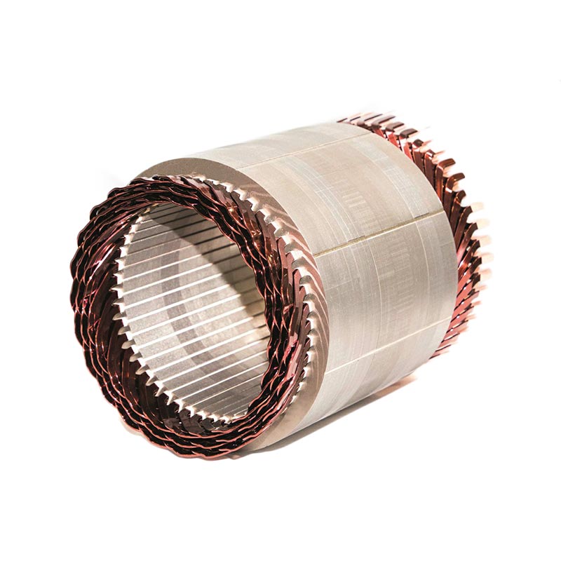
Electric traction motor manufacturing is undergoing an irreversible structural transition from random round-wire pull-in winding to flat-wire rectangular copper hairpin (I-pin / U-pin) architectures. In automotive, commercial transportation, and naval propulsion projects engineered near industrial centers like Charlestown, powertrain developers demand power densities exceeding 50 kW/liter and continuous slot fill factors above 73%. Achieving these thresholds requires complete mastery of wire forming, crown insertion, and end-turn twisting kinematics.
Key Process Breakthrough: Conventional round-wire insertion typically yields slot copper fill factors between 40% and 48%, leaving micro-voids that impede conductive heat transfer to the lamination stack. Hairpin technology utilizes precision-drawn rectangular copper conductors coated with polyimide (PI) or PEEK enamel, achieving slot fill factors up to 78% while lowering thermal resistance across the stator core by 30% to 40%.
Multi-Stage Tooling Sequence: From Raw Conductor to Stator Core
The modern hairpin insertion process requires an integrated series of mechanical and electrical stations that operate synchronously. A single mechanical misalignment or uncompensated wire spring-back during insertion will inevitably shear the slot liner paper (B-stage Nomex or DMD composite), causing an irrecoverable dielectric breakdown under high voltage (hipot testing > 2.5 kV).
01
Wire Straightening & Stripping
Continuous CNC decoiling with multi-plane precision rollers, mechanical or fiber-laser insulation stripping at both lead terminations with micron-depth control.
02
3D CNC 2D/3D Pin Bending
Servo mandrel bending dies shape the U-turn crown. Real-time angular spring-back compensation maintains crown radius symmetry and leg pitch parallelism.
03
Basket Pre-Nesting & Insertion
Multiple layers (4, 6, 8, or 10 conductors per slot) pre-gather into a precision ring basket. A multi-ton high-speed servo ram executes axial push into the stator lamination slots.
04
Dual-Ring Leg Twisting & TIG/Laser
Concentric inner and outer twisting rings expand and index hairpin tips into welding pairs, ready for 3D laser vision tracking and fiber laser beam fusion.
Hairpin Stator vs. Conventional Stranded Round-Wire Architecture
A comparative engineering evaluation across electrical, thermal, and manufacturing metrics:
| Engineering Parameter |
Conventional Round-Wire Stator |
Automated Hairpin Stator Line |
Technological Advantage |
| Slot Fill Factor (%) |
42% – 48% (Theoretical max ~50%) |
70% – 78%+ |
Drastic reduction in DC copper losses; smaller frame size for equal torque. |
| Thermal Conductivity to Core |
Poor; air pockets within winding act as thermal insulation. |
Direct surface contact; minimal potting voids. |
Lowers peak hotspot temperatures by 15°C – 25°C under continuous load. |
| End-Turn Overhang Length |
Elongated, bulky round bundle loops. |
Short, structured end-turn crowns; reduced by 25%. |
Saves up to 18% expensive copper mass; shortens total motor axial envelope. |
| Automation Repeatability |
Variable manual lead routing and lacing. |
100% deterministic CNC servo kinematics. |
Eliminates operator variability; defect rates driven below 50 PPM. |
| High-Frequency AC Losses |
Lower skin-effect impact at standard frequencies. |
Mitigated via multi-layer transposition (8 to 10 layers). |
Permits ultra-high switching frequencies in SiC/GaN inverter systems. |