Industrial Rotor & Stator Automation Systems & Core Assemblies
Engineered to deliver high cycle rates, sub-micron dynamic balancing, and complete traceability across high-volume electric motor manufacturing setups.
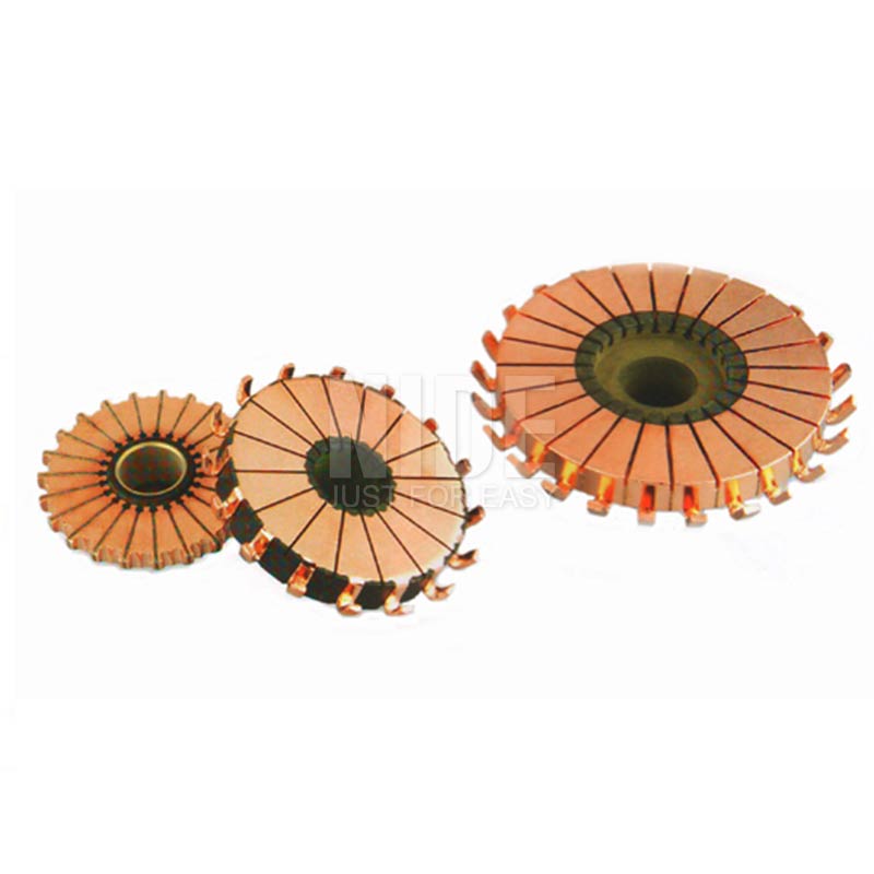
Planar Type Commutator Motor Component (NDPJ-HXQ-39) CE Certified
- High copper thermal tolerance
- Precision planar turning grade
- Low brush sparking profile
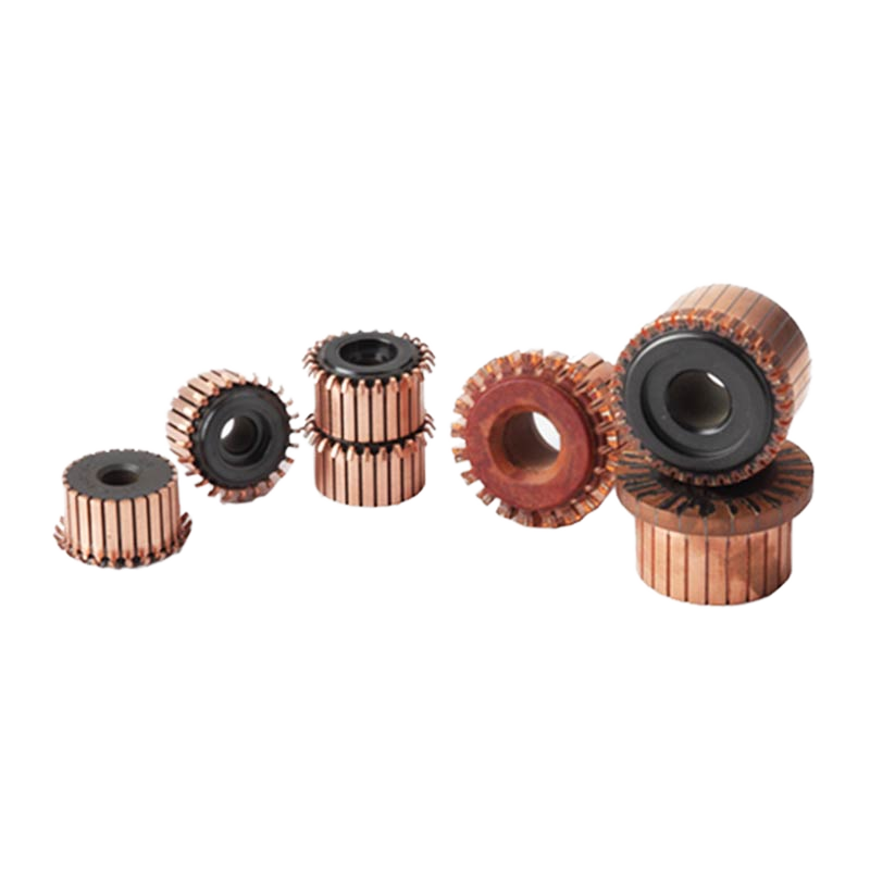
24 Segments Hook Type DC Motor Armature Commutator NDPJ-HXQ-14
- High burst-speed containment
- Automated hook fusion ready
- Starter & grinder motor rated
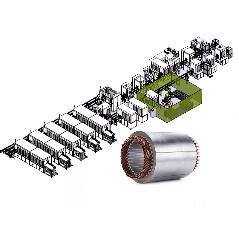
Fully Automatic EV Hairpin Motor Stator & Rotor Assembly Line
- Full flat-wire continuous cell
- Automated 3D laser welding
- Inline partial discharge test
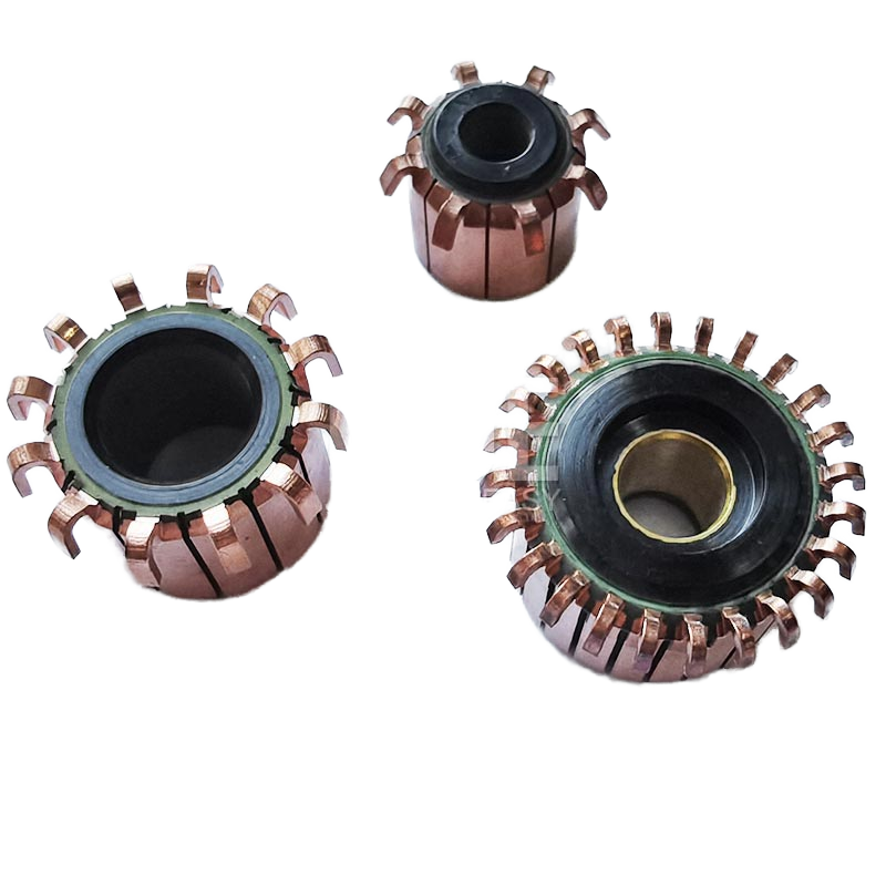
Universal Mixer DC Motor Armature Commutator NDPJ-HXQ-183
- Molded mica inter-segment bar
- High torque kitchen appliance
- Dynamic dynamic run-out checked
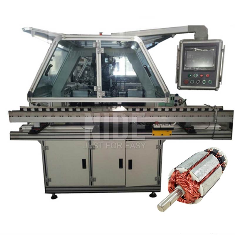
PLC Controlled Armature Rotor Flyer Winding Equipment
- Dual flyer ultra-speed cycle
- Servo-guided tensioner unit
- Automated hook latch & cut
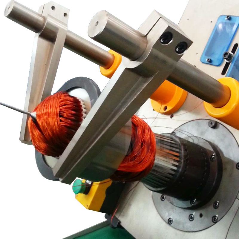
Three-Phase Stator Coil & Slot Wedge Inserting Machine
- Synchronous wedge & coil push
- Zero enamel abrasion system
- Adjustable stack height travel
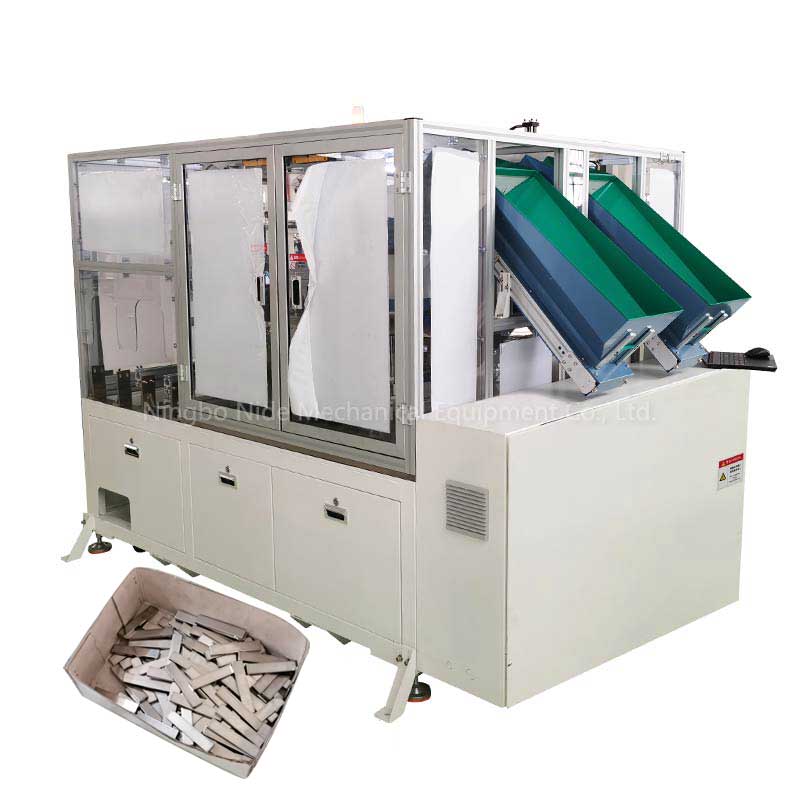
Automatic BLDC Motor Rotor Permanent Magnet Inserting Cell
- Automated epoxy dispensing
- Polarity detection verification
- Multi-pole IPM & SPM insertion
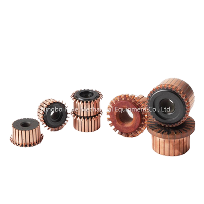
High Precision DC Armature Collector Slip Ring Commutator
- Silver-copper alloy contact
- Integrated rotor fan coupling
- High dielectric breakdown limit
Consulting with Senior Motor Automation Engineers?
Submit your rotor stack drawings, stack height, lamination profiles, and target cycle time for an engineered line assessment.
Engineering State-of-the-Art Rotor Automation Lines: The Definitive Industrial Benchmark
Modern electric motor fabrication requires strict adherence to tight manufacturing tolerances, driven by rising efficiency mandates such as IE4 and IE5 standards, along with high-rpm requirements in electric vehicle (EV) drivetrains and precision BLDC devices. A top-tier rotor automation line functions as an integrated cyber-physical manufacturing system. It combines precision metal forming, automated high-speed flyer or needle winding, automated commutator hot staking or laser welding, dynamic balancing, inductive trickle varnishing, and 100% end-of-line (EOL) electrical quality inspection into a unified, traceable process.
Historically, motor armature manufacturing was bottlenecked by manual interventions—particularly in slot paper insertion, commutator lead hooking, dynamic balancing weight adjustments, and run-out rectification. Today, premier manufacturing lines engineered by specialist factories deliver Overall Equipment Effectiveness (OEE) metrics exceeding 88%, cycle times below 8 to 12 seconds per rotor assembly, and scrap rates below 0.05%. Achieving these results requires an integrated approach that connects individual machine mechanisms with advanced digital servo architectures and factory-wide MES execution frameworks.
Shaft Press & Core Stacking
Continuous servo-controlled hydraulic or electromechanical press-fit systems with real-time force-displacement (F-S) monitoring to prevent shaft distortion and core skewing.
Dynamic Multi-Axis Winding
Multi-flyer and multi-nozzle needle winding with active closed-loop electronic wire tension feedback, safeguarding the dielectric enamel layer of heavy-gauge magnet wires.
Closed-Loop EOL Metrology
Comprehensive electrical testing stations validating weld joint resistance (micro-ohm rating), hi-pot dielectric integrity, surge insulation, and total radial run-out verification.
Strategic Procurement Trends Shaping Rotor Automation Lines
How global tier-1 OEMs and electric motor manufacturers balance automation capital expenditure, flexibility, and high-efficiency performance metrics.
Procurement teams sourcing rotor automation equipment face distinct market shifts. Volatile magnet pricing, new copper hairpin stator implementations, and rising demand for brushless traction powertrains require versatile machine architectures. Leading industrial buyers are adjusting their Request for Proposal (RFP) criteria based on the following key operational trends:
1. Modularity and Fast Product Changeover (SMED Compliance)
The era of single-motor dedicated production lines is fading. Sourcing departments now demand modular automated rotor cells capable of handling 4 to 8 rotor variants with minimal tooling changeover times (under 15 minutes). This agility relies on automated recipe recall via industrial HMIs, servo-adjustable gripper axes, quick-clamp lamination mandrels, and motorized coil-winding pitch settings.
2. Transition from Hot Staking Resistance Welding to Fiber Laser Fusion
While traditional hot-stake resistance fusing remains reliable for standard DC armatures and consumer appliance commutators, high-density EV powertrains and high-output starter armatures are moving toward fiber laser welding. Laser processes create a focused, low-heat-affected zone (HAZ), eliminating mechanical electrode wear, reducing inter-segment thermal degradation, and establishing superior metallurgical bonds between copper wire leads and commutator segments.
3. Zero-Carbon and Low-Energy Thermal Impregnation
Standard solvent-borne varnishing ovens consume significant thermal energy and emit VOCs. Current procurement standards prioritize high-frequency induction heating trickle varnishing or ultraviolet (UV) curing resins. These methods deliver localized, energy-efficient resin penetration into rotor slot cavities within 90 seconds, compared to the 45-minute cycles typical of older thermal convection ovens.
4. Direct Process Traceability (Industrial IoT & Machine Vision)
Every rotor moving along the automation transfer line now receives a laser-etched 2D DataMatrix code at Station 01. Downstream stations (shaft press-fitting, winding, fusing, balancing, and testing) log real-time process data into a localized OPC-UA server. This architecture ensures complete traceability: if a balancing anomaly or hi-pot test failure occurs, the line automatically diverts the affected rotor to a quarantine siding with full diagnostic reports.
| Automation Subsystem | Conventional Tooling Architecture | Advanced Next-Gen Specification | Procurement Impact & ROI Metric |
|---|---|---|---|
| Flyer Winding Cell | Pneumatic wire tensioning, static indexing, mechanical slip clutches | Dual-servo electronic active tension control, digital recipe recall, automated hook clipping | 40% drop in wire enamel strain micro-cracks; eliminates manual adjustment downtime during wire spool swaps. |
| Commutator Connection | Tungsten electrode AC/DC resistance fusing, periodic electrode dress cycles | High-brightness multi-kW fiber laser welding with real-time optical seam tracking | Zero consumable electrode costs; down to 0.01 mΩ resistance consistency across 24+ segments. |
| Dynamic Balancing | Manual drill correction, single-plane static inspection, manual balance weights | Automated dual-plane milling/molding station with closed-loop laser displacement feedback | Guarantees G1.0 balancing tolerance with under 10-second tact times, eliminating downstream motor whine and bearing wear. |
| Magnet Assembly (BLDC) | Manual magnet slot insertion, room-temperature single-part adhesives | Robotic multi-axis magnet feeding, vision-verified polarity, automated dual-cure structural bonding | Eliminates manual polarity errors; high-speed push insertion yields 99.98% first-pass pass-rates. |
Manufacturing Infrastructure & Technical Capabilities
Combining over 14 years of electric motor engineering expertise with an integrated 30,000+ square meter manufacturing footprint.
Established in 2010 in Ningbo, Zhejiang, Ningbo Nakro Intelligent Equipment Co., Ltd. builds specialized automation equipment for the global electric motor industry. Rather than relying on simple third-party machinery integration, Nakro operates specialized engineering and CNC fabrication facilities. Here, critical wear components—including high-precision tungsten winding flyers, carbide coil-insertion blades, and dynamic balancing mandrels—are machined in-house under strict ISO 9001 quality management systems.
Nakro acts as a full-service technical partner, delivering complete production machines alongside matched high-precision components like commutators, ball bearings, carbon brushes, and shaft blanks. This integrated model ensures line tooling and motor materials work together smoothly from the first factory trial run to final high-speed mass production.
2010
Year Established
50+
Export Countries
30k+
m² Factory Scale
< 0.05%
Target Scrap Rate
Comprehensive Turnkey Engineering Protocol
Every rotor line project progresses through a five-stage engineering development protocol designed to mitigate capital risk for overseas manufacturers:
Stage 1: DFM & Drawing Review: Our sales and design engineers assess your rotor lamination profiles, wire gauge elasticity, slot insulation parameters, and target line output to optimize tooling geometry.
Stage 2: Line Simulation & Layout Design: Detailed station-by-station line layouts, pallet cycle timing, and buffer designs are modeled to fit your factory floor plan and eliminate production bottlenecks.
Stage 3: Precision Build & In-House Tooling: Automated assembly stations, control cabinets, and precision mechanical arms are assembled with genuine components from brands like Mitsubishi, Omron, SMC, and Schneider.
Stage 4: Factory Run-Off with Real Materials: Before international shipment, the automation line completes multi-hour continuous dry and wet runs using your specified laminations, wire spools, and commutators.
Stage 5: On-Site Commissioning & Global Support: Nakro engineers support field installation, train operators, optimize line cycle times, and provide long-term tooling supply and remote diagnostic access.
Frequently Asked Questions: Technical Due Diligence for Rotor Lines
Real-world engineering answers to critical questions faced by industrial procurement teams before investing in high-speed automated rotor lines.
What is the standard cycle time (tact time) for a fully automated universal armature line?
For standard universal motor armatures (such as those used in power tools, blenders, and vacuum cleaners with 12 to 24 slots), a modern automated rotor line achieves a finished station takt time between 8 and 14 seconds per piece. This speed is supported by parallel dual-flyer winding cells feeding into a centralized high-speed fusing, balancing, and testing conveyor loop.
How do Nakro machines prevent copper wire insulation damage during high-speed flyer winding?
Our winding systems use closed-loop electronic tensioning heads with active servo motor feed compensation. Unlike friction-based tensioners, our systems monitor wire acceleration and deceleration in real time. Combined with mirror-polished tungsten carbide wire guides and ceramic rollers, this setup keeps tension fluctuations within ±3%, preventing enamel elongation and micro-fissuring.
Can the rotor line handle different motor models on the same production shift?
Yes. Lines are designed following SMED (Single-Minute Exchange of Die) principles. Adjustments to core stack height, shaft lengths, and commutator positions are managed via motorized servo presets stored in the HMI. Mechanical tooling changes (such as winding flyer formers and balancing collets) feature quick-lock bayonet mounts, enabling full changeovers in under 15 minutes.
What acceptance criteria are verified during the Factory Acceptance Test (FAT)?
The FAT protocol covers a 100% full-speed trial run using customer-provided laminations, copper wire, and shafts. Key parameters checked include line cycle time, Overall Equipment Effectiveness (>88%), dynamic balance capability (G1.0/G2.5), weld electrical resistance continuity, hi-pot dielectric strength, and safety interlock functionality. Detailed run-off video recordings and inspection reports are signed off prior to export release.
What overseas maintenance and service support is available for international clients?
With equipment deployed in more than 50 countries, we maintain an established network of regional service partners supported by our internal field engineering team. All lines include integrated VPN industrial routers for remote PLC and HMI diagnostic support. We also provide on-site commissioning, operator maintenance training, and stocked replacement wear parts (such as winding needles, stripping blades, and collets).
How is high-speed dynamic balancing accomplished without damaging the rotor core?
Our balancing stations use dual-plane optical vibration detection to calculate the unbalance vector. Correction is performed by clean servo-controlled axial or radial end-ring milling cutters, or by automated structural epoxy dispensing. Both methods strictly preserve the lamination stack's magnetic flux paths while holding vibration within specified operational limits.
Ready to Optimize Your Rotor Automation Output?
Send your motor drawings, target cycle times, and factory layout requirements to our engineering team for a detailed line proposal, station sequence breakdown, and budget estimate.
