Featured Rotor Manufacturing & Assembly Systems
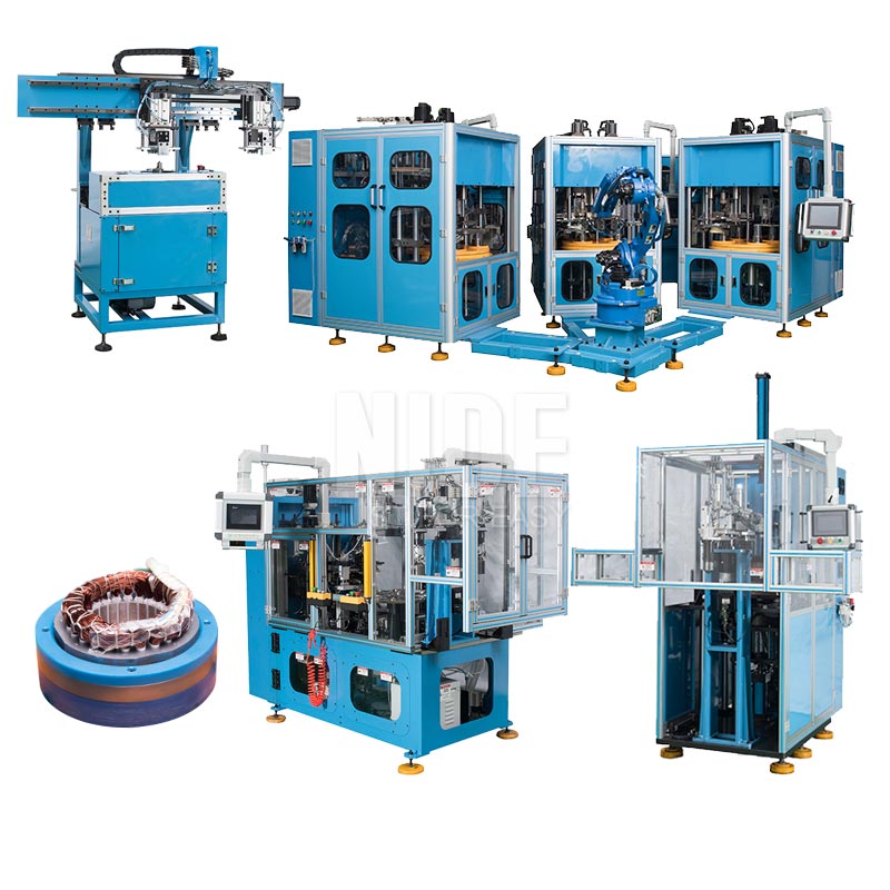
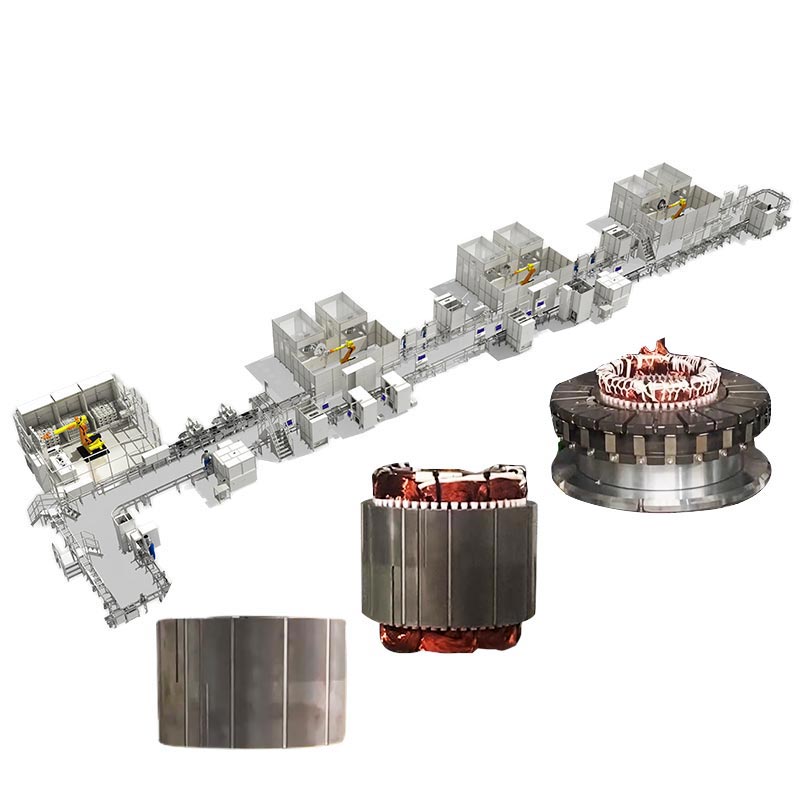
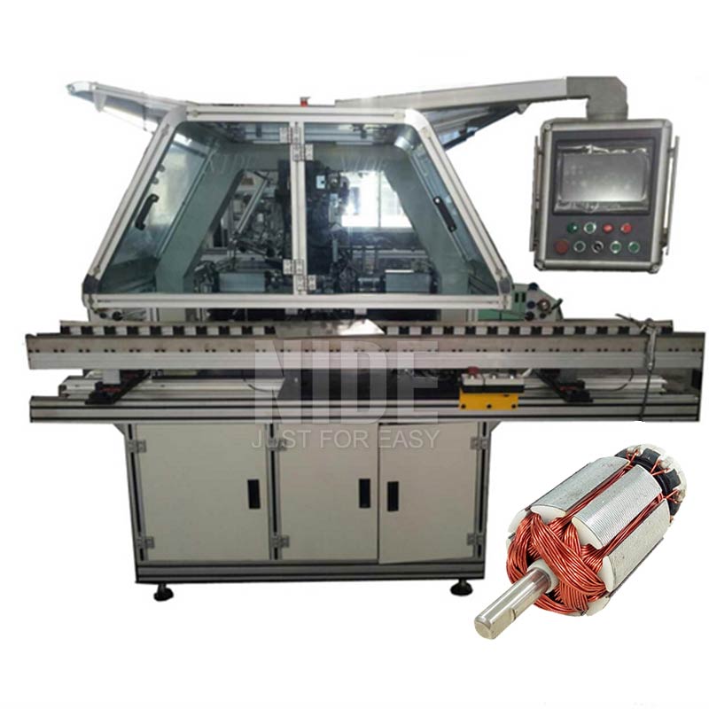
Integrated turnkey rotor winding, precision balancing, stator coil insertion, and high-spec motor hardware engineered for tier-1 suppliers and contract manufacturers in Texas.
Engineering Whitepaper: Precision Rotor Balancing in Modern DFW Manufacturing
The manufacturing ecosystem of the Dallas–Fort Worth (DFW) Metroplex—spanning aerospace hubs around Grand Prairie and Fort Worth, electric vehicle engineering corridors along the I-35 corridor, commercial HVAC compressor manufacturing, and mission-critical data center pumping systems—faces an unprecedented demand for operational velocity and rotational precision. As rotational speeds in brushless DC (BLDC) motors, permanent magnet synchronous motors (PMSM), and micro-turbines surge past 20,000 RPM, residual mechanical unbalance ceases to be a mere acoustic annoyance; it becomes a catalyst for catastrophic bearing fatigue, structural resonance, and premature system failure.
As China’s preeminent manufacturer and technical supplier of automated rotor dynamic balancing lines, Ningbo Nakro Intelligent Equipment delivers advanced engineering architectures directly to Dallas enterprises. Rooted in rigorous compliance with ISO 21940-11 and ANSI S2.19 balance quality grades, our continuous multi-station balancing cells reconcile high-throughput capacity with sub-micron measurement repeatability. By replacing legacy batch balancing and manual trial-mass protocols with fully closed-loop CNC robotic de-weighting, our solutions empower North Texas production facilities to eliminate bottleneck operations while achieving flawless balance grades down to G0.4 and G1.0.
The Physics of Rotor Dynamics: Static vs. Couple vs. Dynamic Unbalance
Every asymmetrical mass distribution along a rotor’s longitudinal axis produces a centrifugal excitation force governed by $F = m \cdot r \cdot \omega^2$, where $m$ denotes the unbalance mass, $r$ represents the radial displacement from the rotational centerline, and $\omega$ represents angular velocity. Because this force scales quadratically with angular velocity, a rotor operating with marginal unbalance at 3,000 RPM generates sixteen times the destructive dynamic load when spun at 12,000 RPM.
Industrial rotors typically manifest three distinct mechanical imbalances, all of which must be addressed dynamically in a single automated fixture:
- Static Unbalance: The principal inertia axis is displaced parallel to the geometric shaft centerline. While measurable in a non-rotating state, static balancing fails to neutralize axial rocking couples.
- Couple Unbalance: The principal inertia axis intersects the shaft centerline precisely at the center of gravity, generating two equal forces $180^\circ$ apart that create violent angular moments under operational velocity.
- Dynamic (Dual-Plane) Unbalance: The standard reality in electric motor armatures and turbomachinery rotors, where the principal axis of inertia is neither parallel nor intersecting the geometric axis. Neutralizing dynamic unbalance necessitates synchronous vector extraction across two discrete correction planes (Plane A and Plane B).
Nakro’s automated balancing lines utilize digital piezoelectric hard-bearing transducer arrays paired with non-contact laser optical tachometers. This setup computes complex vibration phase angles and magnitude vectors within milliseconds, eliminating mechanical resonance distortion and allowing high-volume manufacturing lines in Dallas to maintain uninterrupted quality cycles.
Automated Rotor Balancing Line: Functional Stage Architecture
Modern manufacturing in North Texas cannot tolerate disparate islands of automation. Nakro engineering balances high-precision dynamic measurement with robotic de-weighting milling and polar drilling in an interconnected, continuous transfer cell.
Robotic Cartesian or 6-axis articulated pick-and-place with integrated optical shaft runout verification, commutator concentricity checking, and serial barcode reading.
Precision belt-driven or end-driven spin station equipped with calibrated quartz piezoelectric force sensors and optical tachometers running real-time FFT spectrum analysis.
Servo-driven V-milling, axial drilling, or automatic resin dispensing. Variable depth and polar coordinates are dynamically fed via Ethernet/IP directly from station 2.
Closed-loop 100% verification spin. Automated laser marking of residual balance certificates, reject diversion gate, and bi-directional SCADA/MES data integration.
Through this integrated architecture, our automated rotor balancing lines routinely achieve cycle times of under 12 to 18 seconds per finished rotor (including dual-plane spin, mathematical vector transformation, robotic transfer, dual-cutter CNC milling, and post-audit verification). By eliminating manual indexing and human operator inconsistency, DFW plants achieve exceptional scrap reduction and stable, repeatable First-Pass Yield (FPY) rates exceeding 99.8%.
Localized Industrial Applications Across the Dallas–Fort Worth Corridor
The industrial landscape of North Texas is characterized by high-reliability mission-critical requirements. From defense tier-suppliers along the Highway 360 aviation beltway to high-volume commercial HVAC facilities in Carrollton and Plano, our dynamic balancing machinery solves industry-specific vibration challenges:
EV Traction & Auxiliary Motors
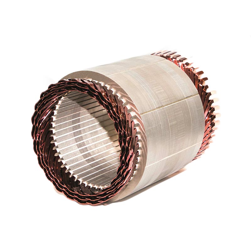
With the rapid growth of clean technology and heavy electric vehicle manufacturing in Texas, hairpin stators and IPM (Interior Permanent Magnet) rotors operate under stringent NVH (Noise, Vibration, Harshness) requirements. Nakro lines provide non-destructive balance correction for high-speed rotors operating up to 22,000 RPM.
Aerospace & Defense Actuators
Serving defense contractors and avionics manufacturers throughout Fort Worth, Arlington, and Richardson. Precision servo armatures, gimbal actuators, and cooling blower rotors require flawless balance integrity under thermal extremes and high G-forces.
Data Center HVAC & Air Handling
Dallas serves as one of the world's most concentrated hyperscale data center regions. The cooling infrastructure depends on continuous-duty EC fans and variable-speed hermetic compressor motors where acoustic emissions and bearing longevity are paramount.
Energy & Submersible Pumping
Supporting the North Texas energy logistics chain, electrical submersible pump (ESP) downhole drive rotors and chemical fluid metering pumps require high-aspect-ratio rotor balancing capable of dampening multi-frequency harmonic flexural vibrations.
Industrial Automation & Robotics
For factory automation systems, Cartesian gantry servos, and automated guided vehicles (AGVs) manufactured in the DFW distribution hub, dynamic rotor stability ensures millisecond positioning accuracy without hunting or servo instability.
Power Tools & Home Appliances
High-volume universal motor armatures for commercial vacuum pumps, angle grinders, and reciprocating saws manufactured or re-manufactured across Texas contract assembly facilities, operating at high rotational speeds up to 35,000 RPM.
Engineering Matrix: Automated Rotor Balancing Line Specifications
The following technical parameters outline Nakro’s primary balancing machine series configurable for production plants in Dallas, Garland, Irving, and Arlington:
| System Attribute | High-Speed Armature Series (NBL-A10) | EV & Traction Rotor Line (NBL-EV40) | Heavy Industrial & Pump Line (NBL-ID100) |
|---|---|---|---|
| Target Rotor Diameter | Φ15 mm – Φ85 mm | Φ80 mm – Φ280 mm | Φ120 mm – Φ450 mm |
| Rotor Weight Range | 0.05 kg – 5.0 kg | 2.0 kg – 45.0 kg | 10.0 kg – 150.0 kg |
| Achievable Balance Grade | ISO G0.4 – G1.0 | ISO G1.0 – G2.5 | ISO G1.0 – G2.5 |
| Minimum Achievable Residual (Umar) | ≤ 0.1 g·mm/kg | ≤ 0.3 g·mm/kg | ≤ 0.5 g·mm/kg |
| Unbalance Reduction Ratio (URR) | ≥ 90% (Single Pass) / ≥ 98% (Dual Pass) | ≥ 92% (Single Pass) | ≥ 90% (Single Pass) |
| Cycle Time (Tact Time) | 10 – 16 seconds | 25 – 40 seconds | 45 – 75 seconds |
| De-weighting Mechanism | Dual-Spindle CNC V-Milling Cutter | Dual-Axis Milling or Multi-Depth Drilling | Multi-Angle Heavy Milling Head |
| Control Architecture | Industrial PC + Real-Time DSP Controller | Siemens S7-1500 or Allen-Bradley ControlLogix | PLC with High-Speed Transducer Interface |
| Electrical Compliance | NFPA 79 / UL 508A / CE Mark Available | NFPA 79 / UL 508A / CE Mark Available | NFPA 79 / UL 508A / CE Mark Available |
Ningbo Nakro: Enterprise Advantages & Global Delivery Systems
Founded in 2010 in Ningbo, Zhejiang, Ningbo Nakro Intelligent Equipment Co., Ltd. has grown to operate over 30,000 square meters of precision manufacturing facilities, exporting turnkey motor production lines to over 50 countries. Our global footprint covers the United States, Germany, Brazil, Mexico, India, and Southeast Asia.
When Dallas procurement teams and engineering directors evaluate Nakro as their machinery source, they gain advantages that domestic integrators and standard trading companies cannot provide:
From lamination stamping integration, insulation insertion, and needle winding to commutator fusing, dynamic balancing, and full-load motor testing, we supply the complete end-to-end line under one engineering roof.
Our balancing algorithms utilize 64-bit floating-point DSP signal filtering to strip away background ambient factory vibrations, ground harmonics, and electrical noise, achieving surgical measurement repeatability.
We support North American clients with remote augmented-reality telemetry, on-site mechanical and software commissioning engineers, and rapid dispatch of critical tooling and wear components.
Machines destined for Dallas plants are custom engineered to integrate seamlessly into American factory grids: 480V 60Hz 3-phase power, NFPA 79 safety wiring, inch/metric switchable interfaces, and Allen-Bradley PLC architectures.
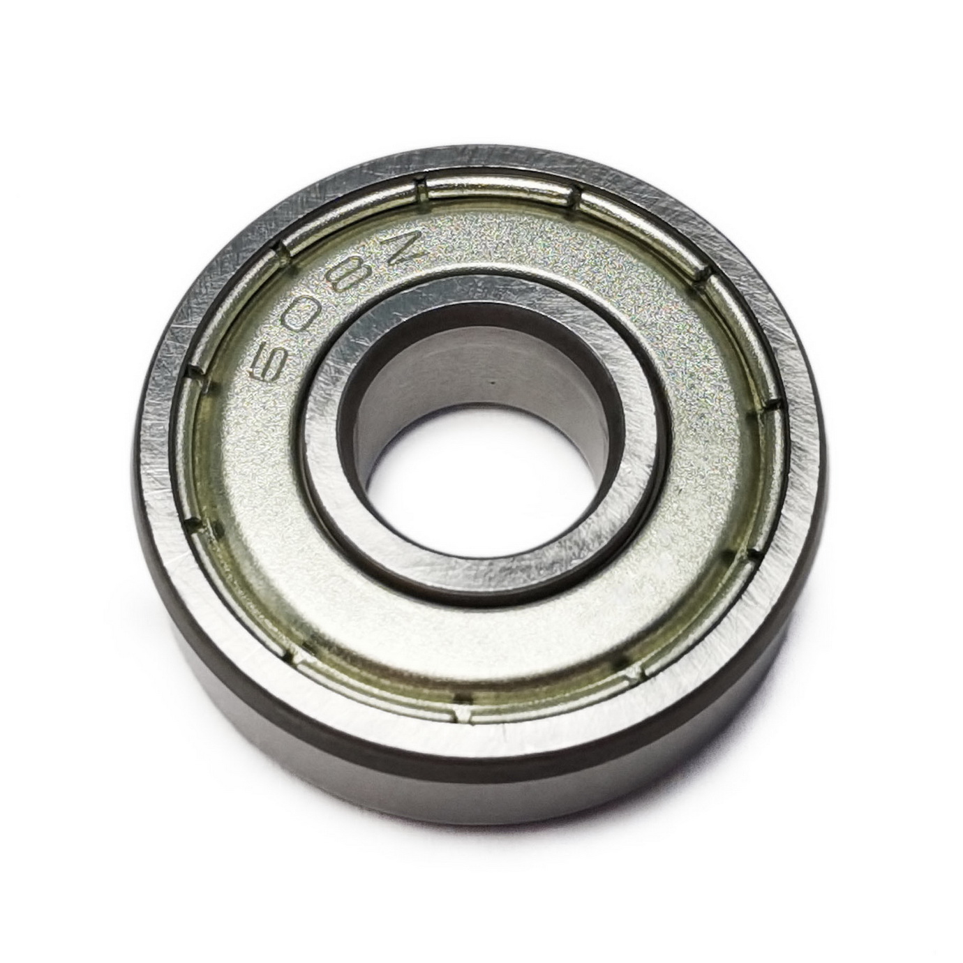
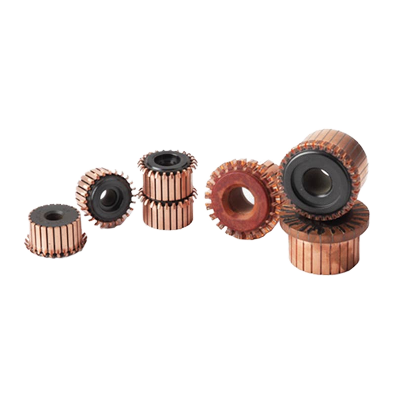
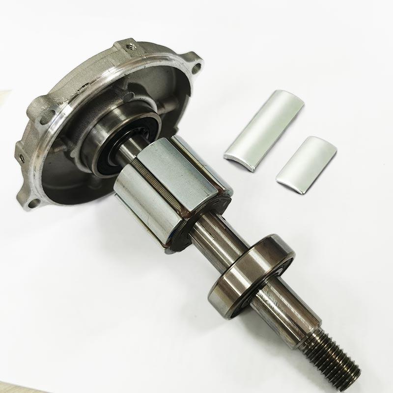
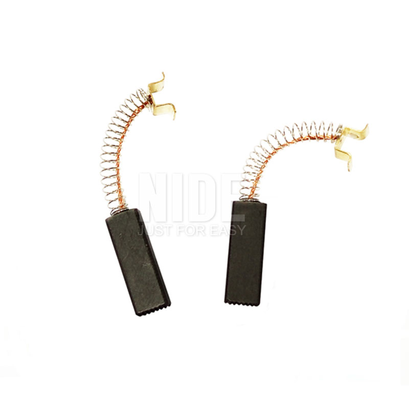
Beyond automated machinery, we supply the precision hardware: custom 608ZZ bearings, 24-segment hook commutators, N52 NdFeB magnets, and low-friction carbon brushes tested for mechanical harmony on our balancing stations.
Prior to crating, every machine runs continuously for 72 hours using the customer’s actual production rotors and wire, validated via full statistical process capability studies ($C_{pk} \ge 1.67$).
Quality Assurance Architecture Before Shipment
Operating under strict ISO 9001:2015 quality governance, Nakro enforces a rigorous six-stage verification protocol on every balancing line:
- Structural Metrology: Machine base castings undergo stress-relief annealing and coordinate-measuring machine (CMM) dimensional checks to guarantee zero mechanical deflection.
- Spindle Dynamic Runout Testing: Balancing spindle bearings are run at maximum design RPM for 12 hours, with temperature monitoring and dynamic radial runout held under $0.002\text{ mm}$ ($2\ \mu\text{m}$).
- Electrical & Control Cabinets: Complete point-to-point continuity, insulation resistance (hipot test), and functional safety interlock audits (Category 4 / PL e safety circuits).
- Mathematical Vector Run-Off: Calibrated master test rotors with certified ISO test weights confirm precision angular resolution to within $\pm 0.5^\circ$.
- Customer Sample Trial Run: High-volume processing of customer-supplied armatures to verify cycle time, de-weighting accuracy, and tool life.
- Seaworthy Packing: Multi-layer vacuum foil barrier, vapor-phase corrosion inhibitors (VCI), and reinforced wooden ocean shipping containers designed for seamless drayage from the Port of Houston to Dallas terminals.
Dallas Procurement & Engineering FAQ: Sourcing Balancing Lines from China
Navigating capital equipment procurement requires clarity regarding technical adaptability, delivery logistics, local codes, and operational support. Below are direct, detailed answers to questions frequently raised by plant managers and procurement directors in the Dallas area:
Can Nakro build balancing lines compliant with US electrical codes (NFPA 79, UL 508A)?
How are logistics, shipping, and customs handled for delivery to Dallas facilities?
Can the balancing control system integrate Allen-Bradley (Rockwell Automation) PLCs?
How does Nakro manage Factory Acceptance Testing (FAT) and Site Acceptance Testing (SAT)?
What is the cutting tool life and replacement process for automated milling correction stations?
How do you handle tooling changeovers for different rotor stack lengths and shaft diameters?
What warranty and spare parts consignment options are provided to US customers?
Turnkey Delivery Timeline for Dallas Manufacturing Facilities
Investing in a capital rotor balancing line requires a structured project management methodology. From initial drawing review to full-rate production in Texas, our engineering roadmap ensures clear milestones and on-time project execution:
Comprehensive CAD evaluation of rotor geometry, lamination stack, allowable milling zones, targeted ISO balance grade, and takt time analysis.
Precision casting fabrication, CNC machining of V-blocks, dynamic spindle assembly, electrical enclosure wiring, and DSP firmware parametrization.
Continuous trial run with customer sample rotors. Statistical process analysis, unbalance reduction ratio verification, and customer sign-off.
Ocean transit to Houston, customs clearance, Texas plant delivery, mechanical leveling, electrical tie-in, SAT approval, and local staff training.
Ready to Modernize Your Rotor Balancing Line in Dallas?
Whether you are expanding high-speed EV motor manufacturing, upgrading aerospace actuator armatures, or automating HVAC motor balancing in North Texas, our engineering team will provide a comprehensive system proposal, cycle time study, and quotation tailored to your motor drawings.
