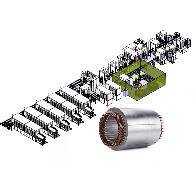
Engineered Precision Portfolio
Featured Dynamic Balancing & Motor Production Machinery
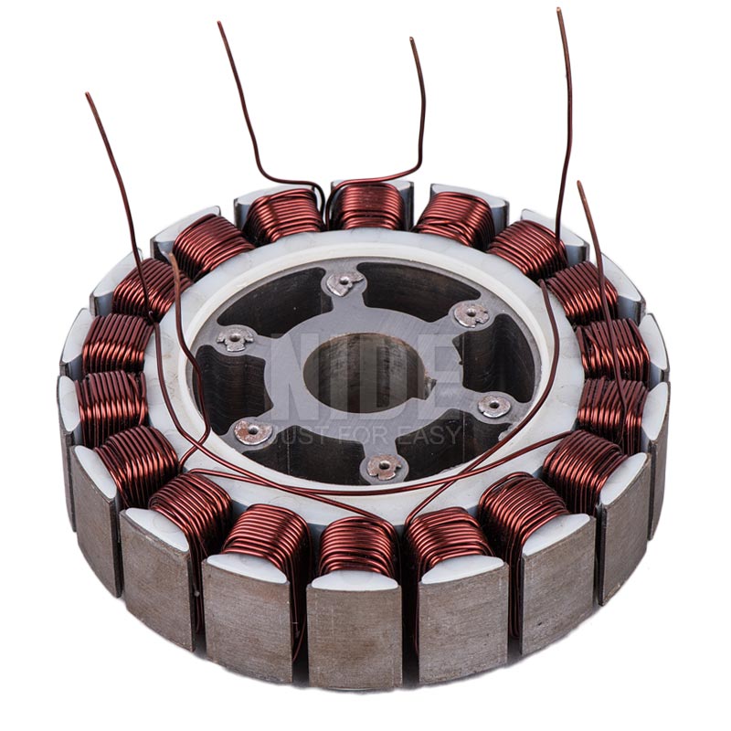
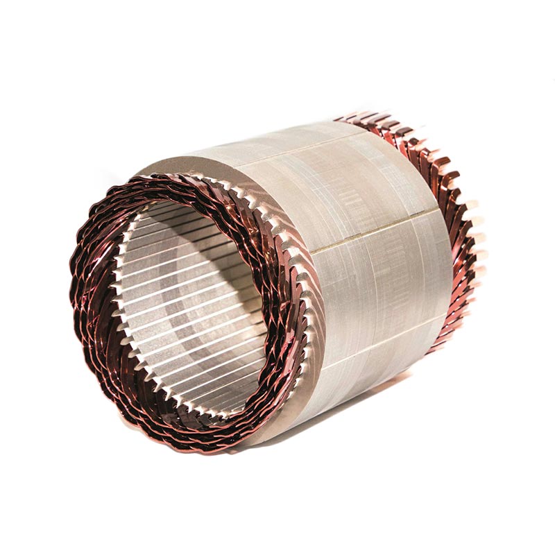
Explore our industrial-grade dynamic rotor balancing solutions, hairpin stator assembly cells, automated coil winders, and certified electromagnetic core components designed for extreme duty cycles.
2010
Established Since
50+
Export Destinations
30,000+
Facility Area (m²)
ISO 9001
Verified Quality Assurance
Technical Authority Whitepaper
Rotor Balancing Metrology: Overcoming High-RPM Dynamics in E-Mobility
As rotor operating velocities exceed 18,000 to 24,000 RPM in modern electric vehicle transmissions and precision spindle systems, dynamic balancing changes from a downstream quality check to a foundational manufacturing requirement.
ISO 1940-1 Grade Compliance
Residual unbalance generates centrifugal forces that scale quadratically with rotational velocity ($F = m \cdot r \cdot \omega^2$). Modern balancing systems must routinely achieve ISO G0.4 or G1.0 quality grades on armatures, high-speed rotors, and drive shafts.
- Sub-micron displacement sensing resolution
- Dual-plane hard-bearing piezoelectric force transducers
- Real-time automated phase-angle separation algorithms
Material Removal vs. Mass Addition
Selecting automated balancing stations depends upon rotor topology. Universal motor armatures utilize high-speed multi-axis milling cutters or axial drilling units, whereas exterior magnet rotors rely on epoxy dispensing or counterweight inserts.
- Integrated chip extraction to preserve magnet lamination
- CNC-controlled continuous contour milling without notch effects
- Automated de-weighting weight tolerance down to ±0.05 mg
NVH & Acoustic Resonance Mitigation
Uncorrected mechanical imbalance triggers high-frequency harmonic vibration that degrades bearing races, accelerates brush wear on commutators, and induces electromagnetic hum across inverter-driven frequency ranges.
- FFT spectral vibration signature analysis at line speeds
- Elimination of mechanical chatter in downstream transmissions
- Direct reduction of radiated acoustic sound pressure levels
| Rotor Application Category | Balancing Class (ISO 1940) | Typical Balancing Method | Target Cycle Time (s) | Permissible Residual Unbalance (Uper) |
|---|---|---|---|---|
| EV Traction Motor Armature (SiC 800V) | G 0.4 - G 1.0 | Automated V-groove Milling / Multi-axis CNC | 22 - 35 s | ≤ 0.1 - 0.5 g·mm/kg |
| BLDC Wheel Hub Motor (Outer Rotor) | G 2.5 - G 6.3 | Adhesive Mass Addition / Laser Balancing | 18 - 28 s | ≤ 1.0 - 2.5 g·mm/kg |
| Automotive Auxiliary DC (Wipers, Blowers) | G 2.5 | Radial / Axial Drilling on Lamination Core | 12 - 18 s | ≤ 1.5 - 3.0 g·mm/kg |
| High-Speed Industrial Spindle & Pump | G 0.4 | Dynamic In-situ Milling & Laser Ablation | 45 - 60 s | ≤ 0.05 - 0.2 g·mm/kg |
Industry Forecasting & Strategic Sourcing
Future Procurement & Technology Trends in Dynamic Balancing
Understand how intelligent sensing, laser material removal, Industry 4.0 data exchange, and complete turnkey consolidation are transforming procurement specifications across global motor plants.
Total Cost of Ownership (TCO) Consolidation
Global procurement teams are shifting away from standalone balancing vendors toward turnkey system integrators capable of orchestrating lamination press-fitting, hairpin winding, commutator fusing, and final dynamic balancing in a continuous kinematic transfer line.
- Single-point accountability eliminates interface friction
- Shared spare parts across winding, lacing, and testing modules
- Reduced capital expenditure via standardized PLC platforms
Non-Contact Laser Balancing Integration
As micro-motors and encapsulated rotors become thinner and more fragile, mechanical milling and drilling induce micro-cracks or delamination. Ultra-fast picosecond and fiber laser ablation stations remove mass in-situ while the rotor spins at calibration speed.
- Zero mechanical clamping stress on delicate silicon steel stacks
- Elimination of cutting fluid and mechanical tool wear
- Single-pass measurement and correction without index cycles
Closed-Loop IIoT & Predictive Metrology
Modern procurement mandates OPC-UA / MQTT industrial connectivity. Dynamic balancing machines now export real-time unbalance distributions upstream to winding and lamination stamping presses, autonomously identifying tooling drift before defects occur.
- Direct integration with MES and SAP production tracking
- Traceable QR-code laser marking correlated to residual unbalance
- Automated preventative alarms for spindle bearing degradation
Why Choose Ningbo Nakro
Global Engineering Capability & Quality Credibility
Over 14 years of dedicated domain expertise in armature manufacturing, stator insertion, dynamic balancing, and end-of-line testing equipment.
ISO 9001 & CE Certified
Every manufacturing cell is designed, assembled, and benchmarked under strict ISO 9001 certified quality management systems with full CE electrical safety verification.
50+ Export Destinations
Proven multi-jurisdictional logistics, customs documentation, and long-term operating partnerships throughout Southeast Asia, Eastern Europe, South America, and the Middle East.
Custom Tooling & R&D Depth
Our in-house design engineering teams configure customized winding nozzles, dynamic balancing fixtures, insertion tooling, and PLC control programs tailored to exact lamination geometries.
One-Stop Component Supply
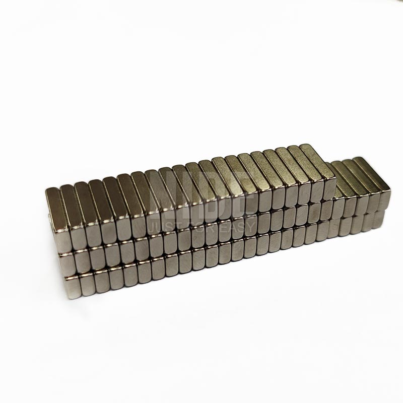
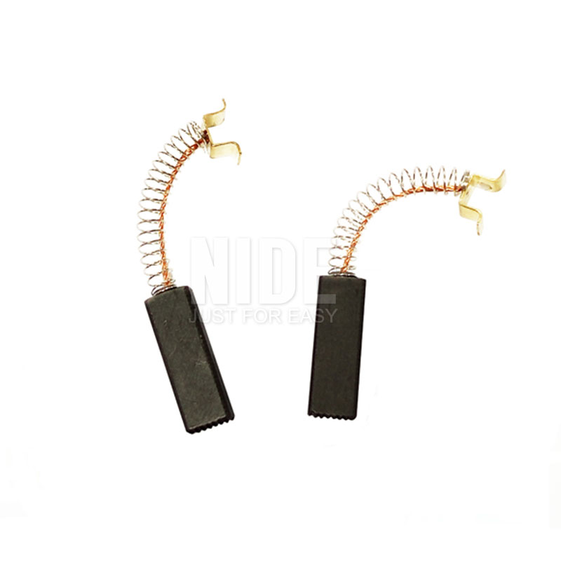
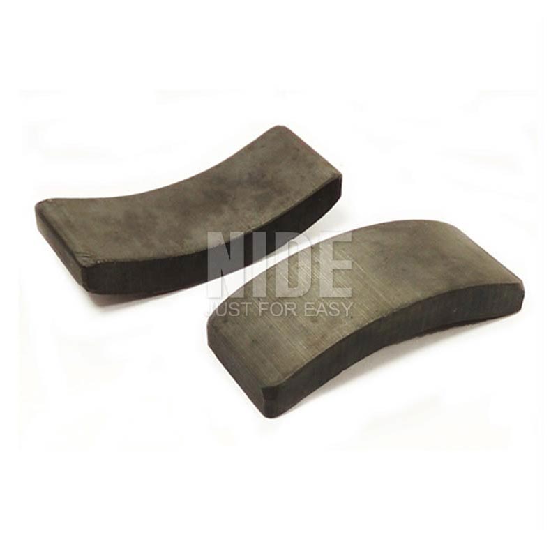
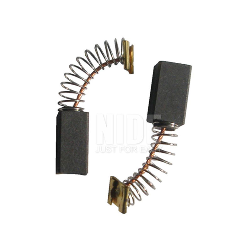
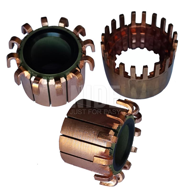
From complete automated production lines to precision commutators, N52 neodymium magnets, carbon brushes, and insulation papers, we provide full supply chain coherence.
Upgrade Your Motor Assembly & Balancing Efficiency
Send us your rotor dimensional prints, target lamination stack heights, and annual production volumes. Our technical team will generate an optimized process layout, cycle-time model, and formal quotation within 24 hours.
Get a Quote
Procurement Guidance
Frequently Asked Questions: Dynamic Balancing & Motor Production Equipment
Clear, technically verified answers addressing machine selection, factory acceptance tests (FAT), tooling lead times, and international after-sales commissioning.
What critical specifications are required to quote a rotor dynamic balancing machine?
+
To provide an accurate technical proposal and cycle-time calculation, our engineering department requires: (1) Rotor 2D/3D technical drawings highlighting bearing journal diameters, core diameter, and total shaft length; (2) Maximum and minimum rotor mass range; (3) Operating rotational velocity and targeted balancing precision grade according to ISO 1940-1 (e.g., G0.4, G1.0, G2.5); (4) Preferred correction method (axial drilling, tangential milling, or manual/automated counterweight dispensing); and (5) Desired cycle time per workpiece.
What is the difference between soft-bearing and hard-bearing balancing systems?
+
Soft-bearing balancing machines operate at speeds above the natural resonant frequency of the suspension system, measuring actual bearing vibration displacement directly. Hard-bearing machines operate substantially below their critical resonance threshold, utilizing rigid cast iron supports equipped with high-precision piezoelectric force transducers. Hard-bearing machines allow permanent calibration for various rotor geometries without test runs, deliver superior operational safety for heavy rotors, and are the industrial standard for modern automated motor lines.
How does Ningbo Nakro verify equipment capability prior to international shipping?
+
Every standalone unit and automated cell undergoes an extensive Factory Acceptance Test (FAT) protocol at our Ningbo manufacturing plant. Buyers are strongly encouraged to provide raw workpieces (stator laminations, copper wire, motor shafts, and commutators). We conduct a continuous multi-hour production trial run to verify cycle times, repeatability, and residual unbalance tolerances. Complete run-off inspection reports, measurement gauge R&R studies, and high-definition video documentation are submitted for official sign-off prior to crating.
Can balancing machines be integrated with upstream coil winding and hot-stacking stations?
+
Yes. Ningbo Nakro specializes in turnkey motor line manufacturing. Our balancing cells can be supplied as self-contained automated modules integrated with gantry robots, pneumatic pick-and-place manipulators, or walking beam conveyor transfers that interface directly with our commutator hook welding machines, armature winding stations, and final electrical surge/hipot testing cabinets.
What warranty, international commissioning, and technical support services are provided?
+
We deliver a comprehensive 12-month mechanical and electrical warranty starting from the date of final site acceptance. We provide worldwide on-site commissioning, installation assistance, and extensive operator training conducted by senior field engineers. Additionally, our equipment features remote industrial VPN access modules, enabling our Ningbo R&D headquarters to execute real-time PLC diagnostic checks, software updates, and calibration troubleshooting for international clients across all time zones.
What payment terms, currencies, and commercial delivery options do you accept?
+
We support standard international commercial arrangements including Wire Transfer (T/T) and Irrevocable Letters of Credit at sight (L/C). Transactions are readily conducted in USD, EUR, or CNY. Shipping arrangements are handled under Incoterms 2020 including FOB Ningbo/Shanghai, CFR, and CIF to major global maritime container hubs, complete with ISPM-15 certified fumigated seaworthy wooden crating.
